This article is for 2 groups of people
- You have decided to ditch those ultra-slow laggy IDEs and you are ready to move all your embedded development to the much more efficient GNU ARM toolchain and you are looking for some guidance of how to start
- You would like to learn more about how the code you wrote for your microcontroller is being built and run as compared to the normal PC code execution.
No matter which of the 2 groups you belong to, this article will try to provide you with a good starting point and point you in the right direction!
When I wanted to learn more about the GNU ARM toolchain so that I could move from IDE based development workflow to a simpler format I was finding it hard to get good information in an easy to absorb format like an article or a tutorial. All I got was some cryptic technical documentation which can take ages to decipher. In this article, I have presented the information I learned in a more digestible manner. I hope you enjoy reading it as much as I enjoyed writing it!
I have written this article keeping a beginner in mind so feel free to skip sections which might feel too basic for you using the Table of contents below. So let’s begin!
How Binaries are Made For Microcontrollers
It is important to understand how the source code you wrote along with the manufacturer provided libraries gets turned into binary executables that can run on a microcontroller.
I am sure all of us reading this article are experienced enough to know how compilers, assemblers and linkers work together to make the final object file. Just for the sake of refreshing our memories let’s have a brief look at a typical toolchain and how our source code transforms while proceeding from one stage to the next.
The diagram below shows this in action.
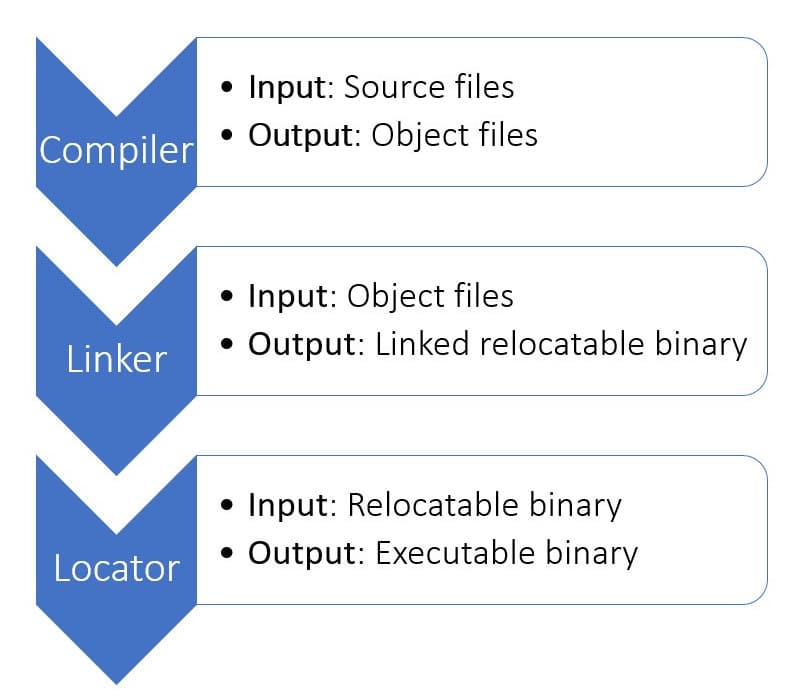
As you can see the entire transformation takes place in 3 steps Compilation, Linking and Locating.
Step#1: Cross-Compilation
In this step, every source file is taken one after the next and the instructions written in higher-level languages like C or C++ are transformed into machine-readable opcodes. If you have ever written assembly language code then you must have seen that assembly level languages mostly support 4 basic types of operations:
- Moving values from one location to another in memory
- arithmetic operation on the values stored in memory and
- logical operation on those values
- Jumping from one execution location to another
These assembly language instructions are also called mnemonics and each of these mnemonics has an equivalent in binary. For example, ADD operation may be represented in binary as 11001010b on an 8bit microcontroller. The compiler’s job is to turn the source code instructions into these a list of binaries and produce a file called as an object file.
Hence the duty of the compilers is to translate the code written in a high-level language into machine-readable opcodes.
Compilers vs Cross-compilers
This translation from mnemonics to opcodes varies from processor to processor. For example, the same ADD instruction may be represented as 10101111110000111000100011101001b in a 32bit processor!
This translation also depends upon the processor’s architecture. ARM architecture may have a different opcode translation as compared to x86 and x64 architecture that computers and laptops use.
Also, opcode for ARM A-series processor architecture used in smartphones will be different as compared to ARM M-series architectures used in microcontrollers! To take it a step further, ARM M0 architecture used on low-end microcontrollers will have a different translation as compared to ARM M3 architecture used on mid-range microcontrollers!!
Hence the duty of the cross compilers is to translate the code written on one machine (our PCs) to make it run on another architecture (our microcontrollers!)
The main difference between compilers and cross-compilers is the fact that the produced binaries can only run on the target machine and not on the native machine!
Step#2: Linking Object Files
After each individual file is compiled into object files, the next step is to link them all together into one single binary. The code we write is usually divided into 3 sections and put into 3 buckets namely
- .text
- .data and
- .bss
The .text bucket gets loaded with the code we write, .data bucket receives the initialized global variables and .bss bucket gets the uninitialized global variables.
As we know, high-level languages give us the ability to divide the entire project into individual files so that we can organize our code better into multiple modules and files. If we were not able to divide our projects into files and modules, we would be stuck with a single file with a million lines of code! Good luck maintaining that kinda code!
The Linker’s duty is to take all these object files and stitch them together into a single binary. It does this function by simply taking all the .text sections in the object files and putting them into one big .text bucket. It does the same for .data and .bss sections by putting them in another big .data bucket and yet another big .bss bucket!
Now after Linker is done with our code we have a huge million line code file made up of opcodes for the machine to read and execute!
Step#3: Locating Binaries
Now that we have a single binary, we need to somehow organize the information present inside it so that it is compatible with what our microcontroller is expecting. Microcontrollers of different sizes have different memory maps associated with them. If you look at the datasheets of microcontrollers you will find a section named “Memory maps”. The screenshot below shows the memory map of the STM32F401 microcontroller.
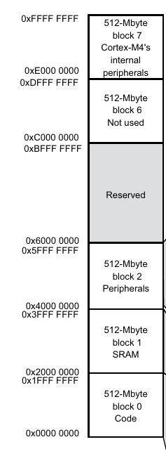
As you can see above the address from 0x0000 0000 to 0xFFFF FFFFF has been divided among the RAM, flash memory, and peripherals. It is the duty of the locator to stamp the correct addresses to the .text, .data and .bss sections so that once everything is loaded into the microcontroller’s flash memory, the .data can be copied to the RAM once the microcontroller is powered up. The code that is responsible for this “copying from flash to RAM” is called the startup code.
The Startup code
In all microcontroller projects there is usually a special file called startup file. This file is usually named as “startup.asm” or “startup.c” or “crt0.s” (stands for C Runtime)
Once the microcontrollers are powered ON, they are hardwired to go to a predefined location and start running the code from there. Usually, this location is the address 0x0000 and this is the location where the startup code lives.
The duty of the startup code is to take the machine from power-on point to the point where the main() function starts executing the application code.
Between power-on and main() function starting, a number of important initializations are made which include the following
- initializes the important peripherals
- the initialized global variables are copied over from the flash to the RAM. (we cannot do this while loading the code to the microcontroller because the RAM is volatile memory!)
- The stack and heap are initialized on the free space of the RAM
- main() is called
During the locating process this startup code must be placed at address 0x0000 and all the sections must be labeled with correct addresses so that the microcontroller can do the rest!
On PCs the operating system does this step at the time the program is loaded and run (also known as loading time). This locating step is only applicable to embedded programs and we need this special step of locating the code to assign addresses to various sections to make the relocatable binary produced by the linker into an executable binary that the microcontroller can run/execute.
Binary production for PCs vs microcontrollers
Let’s have a brief comparison between the PC and microcontroller binary production processes.
| PC | Microcontrollers |
| Only 2 steps: Compile and Link, locating is done at the loading time | Need 3 steps: compile, link and locate |
| Need native compilers | need cross-compilers |
| no need for startup code | Need a special startup code which is different for each microcontroller |
Loading and Debugging
Now that we have learned how the binaries are made for microcontrollers, let’s have a look at how to load the code into microcontrollers and how to debug them!
Loading the executable binary onto microcontroller’s flash memory
This is the next step, load the damn binary onto the flash!! This process is officially known by the terminology “In-System Programming” but you will hear the term “Flashing” to refer to the same process!
To load the program onto the flash and to debug microcontrollers come with a special peripheral known as the debug controller. The protocol implemented may differ between manufacturers but the 2 famous protocols are SWD and JTAG. If you are interested in learning more about JTAG and SWD I suggest you read my other article in the link below.
SWD vs JTAG: Differences Explained!
Each of these protocols can be thought of as a different signaling language. Your PC can speak none of these languages and hence we need to do some translation again! This time in terms of electrical signals. This is where USB debug adapters come into the picture. Debug adapters take data through USB signals and convert them into microcontroller readable JTAG/SWD signals.
Thus as we send this binary from the computer’s USB port via debug adapters, the microcontroller’s debug controller peripheral receives it and stores it onto the flash memory.
Debugging the Code
The IDE’s have usually come with little buttons (step in, step over and step out) to step through the source code as it runs. This is again done with the help of the debug controller and the adapter. As we click these buttons, special instructions are sent to the debug controller which in turn controls the processor’s execution state.
Other than stepping through the code we can also set and clear breakpoints, read the memory contents of the microcontroller and other such debugging activities.
The program that runs on our PC that talks to the debug controller on the microcontroller is usually known by the name “Debug server”
Now that we have seen how the entire process works behind the scenes and have a strong foundational knowledge, let’s go to the focus of this article which is using the GNU toolchain!
GNU ARM Toolchain
By this point I hope you have understood that GNU’s toolchain for ARM is only slightly different from their cousins, the regular GNU tools that produce binaries for PCs! Let’s look at some of the tools that you would need as part of your toolchain that produces the executable binaries.
Go ahead and download the GNU ARM toolchain to your computer from this link and let’s go and explore the contents inside!
Once extracting the archive I was presented with a folder and inside the folder, I got all the goodies as shown in the screenshot below.
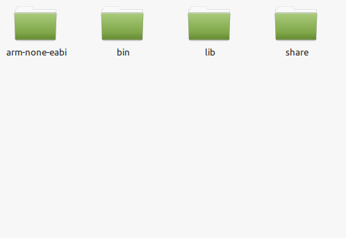
The directory of interest for us is the “bin” directory. Let’s go ahead and open a terminal and navigate into that folder!
Tools to Produce The Binaries
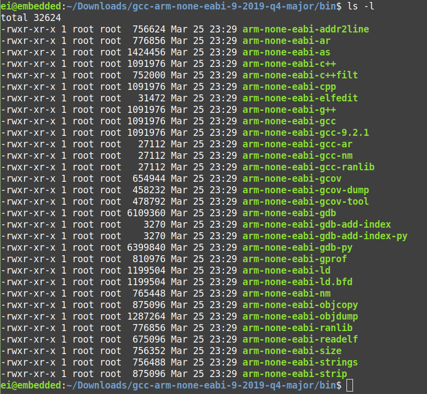
As you can see there are several executables inside that folder. The 4 main files that we need here are
- arm-none-eabi-gcc
- arm-none-eabi-as
- arm-none-eabi-ld and
- arm-none-eabi-objcopy
arm-none-eabi-gcc
GCC stands for GNU Compiler Collection. This is the master driver for the entire toolchain! This tool doesn’t just compile the code, once compilation is doing it calls the linker which does the linking of separate object files into one big file and locates it by giving proper addresses as seen above and produced the final executable!
Hence gcc can be thought of as a driver program for the entire toolchain as it takes care of the entire process and transforms all the source files of a given project into one final executable!
But we can make it stop at any point of the entire process using appropriate options as shown below

arm-none-eabi-as
“as” stands for assembler, it does the translation from assembly language mnemonics into opcodes.
arm-none-eabi-ld
“ld” is the GNU’s Linker and Locator combined into one!
arm-none-eabi-objcopy
There are several formats an object file can be produced in. Popular formats include Extended Linker Format (.elf format) and Common Object File Format (.coff). But these formats are usually for running binaries on PCs and they contain some extra information about the binary.
For microcontrollers, the binaries are usually tightly packed without any extra metadata. objcopy is the tool responsible for taking the elf or coff binaries and pack them in a way that can be flashed onto the microcontroller!
Tools to Help Debug Code
Now that we have seen an introduction of all the tools needed to produce the binaries, lets next look at the tools needed to program and debug the code!
OpenOCD to flash the code
Other than the GNU toolchain for ARM, you need one more piece to complete the puzzle. You need a tool to download the binary onto your microcontroller by talking to the debug controller peripheral by relaying the data through the USB debug adapter. That’s where OpenOCD comes into the picture!
Other than downloading the code OpenOCD also helps in debugging by acting as a middle-man between GDB and JTAG/SWD.
arm-none-eabi-gdb
GDB stands for GNU DeBugger is the debug server we need to handle our debug sessions. GDB helps translate the programmer intentions like
- step through code,
- set breakpoints,
- read variable value,
- read memory content,
- view stack trace, etc
into the form understandable by the microcontroller through some special instructions. These instructions are usually sent through OpenOCD, which in turn adds the necessary headers and relays the messages through the USB debug-adapter to the debug controller peripheral on the microcontroller to step/set breakpoint/whatever you need to do debug your code!!!
And with that, I will conclude this article!
I hope you guys enjoyed this article and learned something useful.
If you liked the post, feel free to share this post with your friends and colleagues!
Related Articles
Here are some of my other articles that might interest you!
Hardware, Software, Firmware, Middleware, Drivers, OS & Applications, The Difference?
Top 14 Alternatives to Raspberry Pi 4B