
Timers play an important role in embedded systems, their duty, of course, is to maintain timing for operations, be it controlling the blinking rate of the LEDs or controlling the sampling rate of the ADCs, or a simple delay on the source code.
Beginners to this field tend to have some trouble understanding the basics of what timers are, what are clock ticks and clock frequencies and why there are so many timer types in a microcontroller. I have written this post keeping beginners in mind, so if you are familiar with some topics you can feel free to skip them and move onto the topics you are interested in!
Clock ticks and clock frequencies
Timers, in essence, are analogous to stopwatches. But instead of counting in seconds they count in ticks.
What are clock-ticks? For the readers hearing the term tick for the first time, it is simply 1 clock cycle. The microcontroller and all its peripherals run with respect to a continuous square wave. That is for every cycle of this square wave, they do one step of operation(run one line of assembly code).
If the microcontroller is a dance floor then the clock ticks are the rhythm that all the peripherals and the processor dance to!
They look something like this
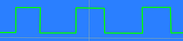
What is an oscillator? The device that produces these square waves is called an oscillator.
What is clock frequency? The maximum speed that the processor can handle is usually denoted using the frequency of this clock which is the number of clock ticks produced by the oscillator per second.
Smartphones and PC processors these days can handle a clock tick in the range of GigaHertz. Just imagine, 1 GHz means 1,000,000,000 times this square wave goes up and down each and every second!
Microcontrollers used in embedded systems usually run at the order of MegaHertz
What is timer-resolution? This is the minimum duration that a timer can measure. For example, If the timer clock frequency is 1MHz then the timer resolution is 1/1MHz = 1 microsecond. Thus the solution can be calculated by the inverse of the clock frequency.
How to convert seconds to ticks? To convert ticks to seconds, we just need to multiply the time in seconds with the frequency of the system.
For example, let’s say we need a countdown timer for 10 seconds. The clock frequency is 1MHz. So the value to be loaded on the countdown timer is 10 x 1,000,000 = 10,000,000 ticks.
If you need to do the reverse, that is change ticks to seconds then all you need to do is divide by the frequency. For example
250,000 ticks = 250,000/1,000,000 = 0.25 Seconds
Need for timers
Let’s take a simple example of blinking LEDs, A client comes to us and asks us to build an LED that blinks every 2 seconds and promises us a million bucks to do so. (Yes, it’s a very nice imaginary deal!)
There are 2 ways we can go about this. One is using the delay instruction and the other is using timers.
Let’s have a look at both the codes.
void main()
{
    set_up_LED();

    while (true)
    {
        turn_LED_on();
        delay(1 second); // just sit and do nothing
        turn_LED_off();
        delay(1 second); // just sit and do nothing
    }
}
Internally delay instruction is implemented as a NO-OPERATION instruction on the microcontroller core. Here the processor just spins around doing nothing just waiting for the time to run out.
For example, in the code above, to make the1 second delay, the processor spins around for 1,000,000 times doing nothing! This is a big waste of both processor’s time and energy!
The more efficient way to do it is via timers.
void timer_interrupt()
{
    if (LED is ON)
    {
        turn_LED_off()
    }
    else if (LED is OFF)
    {
        turn_LED_on();
    }
}

int main()
{
    setup_LED();
    timer_set_time(1second, periodic);

    while (true)
    {
        sleep();  // sleep happily
    }
    return 0;
}
If it’s the first time you are looking at this sort of code, then you will obviously get the feeling that timers make a very simple code into an unnecessarily complicated one. But this could not be further from the truth! Let me try and explain what this code does and what benefits does this longer code brings.
So the idea behind the code is simple. Assume you have a meeting exactly at 12 pm and the time right now is 10 am. There are 2 ways of going about it.
Option 1: Just keep looking at the clock till it reaches 12 pm and then start for the meeting.
Option 2: Keep an alarm on the phone for 12 pm and continue doing something else. Once the time becomes 12 pm, the alarm will beep and interrupt your present work to let you know that you need to leave for the meeting.
Here in microcontrollers, the clock is analogous to the timer, and the processor is you.
The first code we saw above does exactly the steps in option 1. Basically, we wasted the processor’s time.
In the second code, we set the alarm time by loading the timer with the timeout value, then we are turning on the alarm/timer and the CPU goes to take a nap. Once the timer expires, it wakes up the processor and the processor runs the code that is set up to be run if that alarm goes and interrupts the processor, a.k.a interrupt handlers.
Yes, the code looks longer but it lets the microcontroller free to do anything else needed!
Assume our favorite billionaire customer returns after a few days with another requirement saying he needs his device to record temperature and display it on an LCD screen every 3 seconds while the LEDs keep blinking. This could not have been possible with the first set up as the entire time of the processor was occupied to just blinking the LED. But now we can do this using another timer which can count down till 3 seconds as in the following code.
void timer2_interrupt()
{
    take_temperature_reading();
    update_reading_on_display();
}

void timer1_interrupt()
{
    if (LED is ON)
    {
        turn_LED_off()
    }
    else if (LED is OFF)
    {
        turn_LED_on();
    }
}

int main()
{
    setup_LED();
    timer1_set_time(1second, periodic);
    timer2_set_time(3seconds, periodic);

    while (true)
    {
        sleep();  // sleep happily
    }
    return 0;
}
Method one is also known as polling where we wait till we finish the first task before we go for the next one.
Method 2 is called interrupts and it is a very important part of embedded software design.
Thus we are now able to get more things done at lower power consumption, which is a win-win result all thanks to timers!
Timer operation modes
Timers can operate in 2 modes
- One time mode and
- Periodic mode
One-time mode
In One-time mode, we can set the timer to go off after a particular time duration, say 10 ms. Once started, the timer counts down and once it runs out it notifies the core and the timer gets disabled. This action is very similar to using a stopwatch in countdown mode. It is used when we need to start an event at a specified time and it is usually used with processes that are carried out step by step after small delays a.k.a state machines. (like assembling robots which can screw in slot number 1, then waits for the conveyor to move the part a little bit and screws in slot number 2)
Periodic mode
In periodic mode, once the timer runs out, it notifies the core, then instead of getting disabled, it automatically reloads the initial value and starts counting down again. Basically, all this mode does extra compared to the One-time mode is just the auto-restart!
What is the need for the periodic mode in timers? This is needed in 2 scenarios
- In order to measure really long durations.
- In order to routinely perform a task.
The routine performance of tasks has already been discussed in the previous section where we needed to blink an led every 2 seconds. Let’s go ahead and take a look at the use of periodic timers to measure events of really long durations.
Using periodic mode to measure long durations
Usually, the timer ticks are counted and stored on an 8,16,32 or 64-bit register depending on the microcontroller. A 16bit register can count up till 216 -1 = 65,535 (1 is subtracted since counting starts from 0)
Assuming a timer clock frequency of 1MHz, this means that a 16bit timer can count for only 65.36 milliseconds approximately. If we need to measure a duration longer than this, say 10 seconds, then we can use the periodic mode. In this mode, the timer tells the processor when the first round is done through interrupts and then the processor can then increment a variable in its ISR, to keep track of how many rounds are done. Once the expected event occurs, then the processor can go ahead and stop the timer and take note of the present timer value.
Let’s assume the timer value is 100. The variable used to track the number of timer rounds reads 200 at this point. Now we can calculate the total time elapsed by doing a simple calculation. In our case it is 200 x 65.36 ms + 100 = 13.172 seconds.
What is the maximum duration length that can be measured? Now let’s say we use a 64bit integer variable to keep track of the number of rounds/roll-overs of the timer. It can count up till 1.8 x 10¹⁹, this means it can track up to 1.2 x 10¹⁸ seconds or approximately 38368848300 years!
We don’t have to stop there, we can use another variable to keep track of how many times the first variable rolled over and again double it another 64 times! I hope you understood the use of periodic mode and you got the point!
Types of timers
There are 4 types of timers used in embedded systems
- General-Purpose Timers
- Systick Timers
- Real-Time clocks and
- Watchdog timers.
Let’s take a brief look at each one of these and see where to use them in your application.
General-Purpose Timers
These are the normal variety of timers that we have been talking about thus far in this article. Hence I don’t think it needs any further explanation. Let’s have a look at where to use general-purpose timers.
- Predefined time delay to start an event, eg., after I push a button, wait 5 seconds and then turn on the LED
- State machines, eg., assembling robots
- Periodic events, eg., blinking an LED
- Measuring time duration between events, eg, Between measuring the time taken between 2 button presses
Systick Timers
These are special simple timers found in all ARM Cortex-M chips, that has a very limited capability. Unlike general-purpose timers, Systick timers usually have just one mode of operation, which is periodic and decrementing. They can be configured to produce either interrupts and they can also be accessed by polling. The clock used by this SysTick timer can be either the system clock (the clock that is used by the processor) or it can also use a slower reference clock called STCLK (stands for SysTick CLocK)
There are generally used for 2 purposes
- Make time delays and
- Make periodic interrupts
The main idea behind these SysTick timers is that they can be used in Real-Time Operating Systems (RTOS) to produce periodic interrupts, which can then be used for context switching and multitasking. This will make it easier to port the code written on one microcontroller to another with very little changes as the interface with this timer is the same across all ARM Cortex-M chips.
Even though they are designed to be used with RTOS, it can also be used for simple timing purposes.
Real-Time Clock (RTC)
These are low-resolution timers as compared to General purpose and Systick Timers. They are used to provide time in a human-readable form to the end-user and hence their resolution is usually 1 second. Its basic use is to tell the present time to the end-user, in other words, it acts as a digital watch.

It is usually powered separately by a coin cell so that it can keep on running even if the system is switched off. You can also see these coin cells on the motherboard of your computer. This keeps the RTC running even if your computer is plugged out of the power supply.
The implementation can vary depending on the manufacturer. For example on Texas Instrument microcontroller TM4C213G, one of the available general-purpose timers can be configured to operate in RTC mode so there is no separate peripheral to do this. Some manufacturers may have a separate peripheral just for use as an RTC. There are also separate chips sold, that can be added to your project, for use as an RTC. There are hundreds of such chips available with varying accuracies. Examples of these can include DS128 from Maxim integrated products and M48T18 from STMicroelectronics.
Watchdog Timers (WDT).
These are another variety of special timer, whose duty is to make sure the system is functioning properly. Imagine having a buggy software running on your PC and you have appointed your dog to come and press the restart button every time the software becomes unresponsive. Then your dog here is doing the duties of the WatchDog Timer.

Usually embedded system software end in an infinite loop like in the examples we saw above. (the while (true) loop is the infinite loop as the condition remains true all the time and the execution always stays inside this loop) This loop is also called the main loop as the software spends the majority of its time in this loop.
Consider the code snippet below
Here in the main loop, the software takes care of the user tasks first, then it takes care of system tasks. If the software gets stuck somewhere in the user task or system task then we need to reset the system automatically so that the end-user does not have to do it manually himself.
void user_tasks()
{
    // do the tasks asked by the user
}

void system_tasks()
{
    //do the tasks the system needs
}

void pet_watchdog()
{
    // pet him and give him a treat
    reset_timer();
}
void main ()
{
    initialize_system();
    watchdog_set_time(1500);
    watch_dog_start();
    while (true)
    {
        do_user_tasks();
        do_system_tasks();
        pet_watchdog();
    }
}
Let’s say the maximum time duration to perform the user task is 500milliseconds and the maximum duration for the system task is another 1000milliseconds, so every loop must complete at a maximum duration of 1500milliseconds. If it does not happen, then we can assume that the system got stuck somewhere which is undesirable.
So we set the watchdog timer to timeout at 1500milliseconds and at the end of every loop we pet our watchdog and give him a treat for doing a good job, whenever we pet him, his internal timer is reset and then he starts counting down from 1500milliseconds again.
Now if the loop runs longer than 1500 milliseconds our watchdog gets nervous as he is not getting petted and he is not getting his treat. So he goes ahead and resets the system so that it can start performing normal again.
This is how watchdog timers work. I hope you got the idea!
These are the 4 main types of timers used in embedded systems.
You can email us or contact us through this link if you have any questions or suggestions.
If you liked the post, feel free to share this post with your friends and colleagues!