When I heard the term IMU for the first time, I thought it was some cool technology that is beyond my understanding. But once I got some experience playing with it, and got to understand what it physically measures that fear vanished quickly. In this post, I have tried to explain what IMU sensors are, how they work and where and how to use these sensors keeping beginners in mind. So let’s begin.
What is an IMU sensor? IMU stands for Inertial Measurement Unit. An IMU sensor is a combination of an accelerometer and a gyroscope sensor. It is used to detect movements and measure the intensity of movements in terms of acceleration and rotational speeds.
I believe that while we are starting to learn some technologies, especially sensors, a good starting point is learning its application areas first before we actually look into the details of how that technology works internally to help us achieve those applications. This way when we get to the how it works part, we will automatically have those examples running in our minds and the idea behind these technologies will be much easier to grasp. So let’s start with the applications first.
Applications of IMU sensor
Let’s see some familiar examples of how this is useful.
Application #1: smartphones and tablets
I am sure many of us take it for granted of how our smartphones magically change its orientation from portrait to landscape when we tilt our phones horizontally. How does it know which way we are holding the phone? The answer is that it senses gravity.
In physics, we often use this term “acceleration due to gravity” when we talk about gravitational forces. That’s because gravity is measured in acceleration. On our home planet Earth this acceleration due to gravity is 9.81m/s2 (at sea level) and on Moon, it is 1.62 m/s². This is the reason we will feel very weightless on the Moon.
As we saw above, IMU is used to detect movements and measure accelerations and rotational velocity of movements. So IMU can be used to sense the gravity as it can measure acceleration.
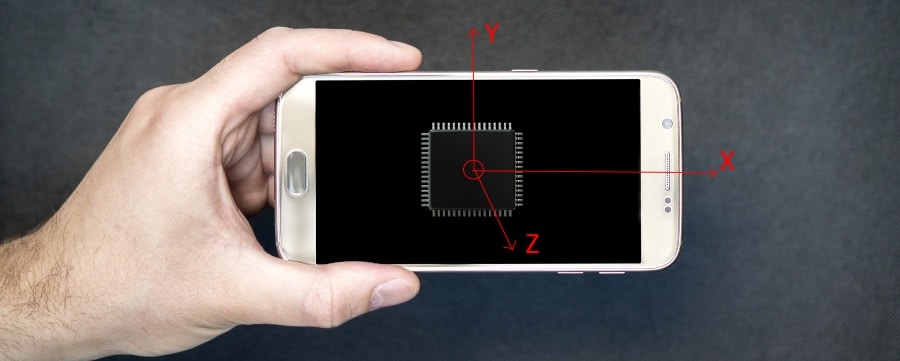
On our phones, usually, an IMU with a 3-axis accelerometer is used to sense the direction on which the gravity is acting on. Have a look at the picture below.

As you can see in the picture, the IMU chip is placed inside the phone and it usually has 3 accelerometers placed in 3 directions. One to measure acceleration along the long side of the phone (X direction), one to measure along the short side (Y direction) and one on the axis that’s coming out of the phone.
If the acceleration due to gravity is measured in the accelerometer placed in the X direction then it means we are holding the phone in portrait mode and similarly if we are holding the phone in landscape mode, then the acceleration due to gravity will be sensed on the accelerometer placed in the Y direction.
When we change the mode in which we are holding the phone, the accelerometer’s readings change and this, in turn, changes the screen orientation for us.
This is just using the accelerometer part of the IMU which is responsible for measuring accelerations.
Application #2: Pedometers
This is another application where the IMU sensor is used. As we walk or run, we create some patterns of acceleration, when our foot hits the ground we decelerate or slow down and when our foot leaves the ground we accelerate. Since these walking and running are natural to us, we just never notice this tiny acceleration, but trust me they are there!

Also when we wave our hands as we move around we also create some little rotational movements, which are useful in sensing the pattern of movement to see if a person is walking or running or staying still.
The pedometers have an IMU sensor which usually is connected to a microcontroller that processes the information from the IMU sensor and tries to see if there is this acceleration and rotational pattern. If it can see that, it simply increments our step counters.
Cheap pedometers usually use some simple data processing algorithm and not so sensitive sensors. Also, they normally don’t use the gyroscope part of the IMU to sense steps. Thus they are usually very inaccurate to count the number of steps walked.
More expensive ones usually learn and adapt to the acceleration patterns of individuals, using more sensitive IMU sensors by processing both the rotational and acceleration data, to determine if a person has just taken a step.
Application #3: VR Headsets
Virtual Reality is an upcoming technology and it’s going to revolutionize the gaming industry. If you have not tried using a VR headset before, I recommend you try one out, it’s a fun way of entering the digital world, it’s something like the Matrix!
If you have a nice budget, you can try getting an oculus rift VR headset (link to amazon), or if you are one a tight budget you can try a cheap alternative like the Xiomi headset or the Google Cardboard (link to amazon) and pair it with your smartphone to get the Virtual Reality experience!
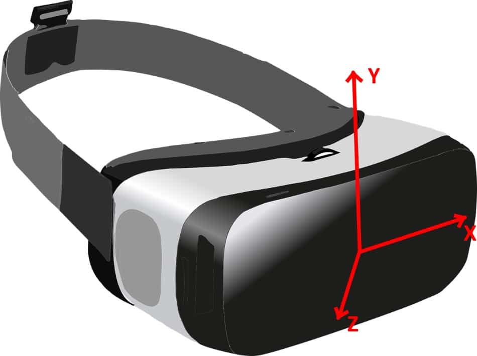
VR headsets mainly use these IMU sensors to keep track of the position your head is in to change the video feed it’s giving out. For example, when you look up, you are essentially rotating your head about the X-axis, and this will be sensed by the gyroscope of the IMU sensor placed inside your VR headset and this, in turn, will give you a video feed of the sky. When you look down, you rotate your head in the opposite direction and you get a view of the ground!
Application #4: Drones, Helicopters, and Aeroplanes
Another application of the IMU sensor is to track the orientation and heading of drones, helicopters, and airplanes.
Usually, these solutions use a combination of IMU sensors along with an electronic compass (a.k.a magnetometer). This combination has the technical name of the AHRS sensor. (Attitude and Heading Reference System)
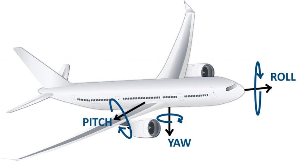
Basically the accelerometer tells us the angle the drone is in with respect to the ground, gyroscope uses this data as reference and calculated the pitch, yaw and roll continuously as the drone is flying around and the magnetometer tells us the direction in which the drone is headed with respect to the magnetic field of our planet, so that we can track it on a map!
What is the difference between IMU and MARG sensors? MARG stands for Magnetometer, Angular Rate, and Gravity, which basically means an IMU in combination with a compass (magnetometer). These are mainly used in aircraft as discussed in this application.
Application #5: Cameras
In cameras, the 2 halves of the IMU sensors, accelerometers and gyroscopes are used separately in 2 separate use cases.
Use of Gyroscopes in cameras
If you are into photography and cameras you would have come across this technology called Optical Image Stabilisation or OIS for short. How this basically works is when we are taking videos, it uses the gyroscope part of the IMU sensor to see if we are rotating the camera, in other words, if we are shaking our hands, so that it can do appropriate corrections by rotating the image in the opposite way so that our videos remain steady, as if we used a tripod!
Use of accelerometers in cameras
Photographers have different styles of holding the camera when they are taking pictures in portrait mode. Some hold it such that the shutter button is on top, while others hold it such that the shutter button is on the bottom. It doesn’t matter if we are holding the camera with the shutter button in the top or bottom, the picture always comes the right way up when we download it to our computers. In this application, accelerometers are used to sense the direction of gravity to detect the orientation of the pictures!
How IMU works?
So now that we have a good understanding of the uses of IMU sensors lets now get into the “How it works?” part. Let’s take the individual sensors, accelerometer and gyroscopes and magnetometers to see how each one works
How do accelerometers work?
Before we start looking at the technical details of how an accelerometer works, let’s go for an imaginary ride in a bus to understand acceleration.
So imagine you are sitting in the vehicle, let’s say a train so that there is more space for our thought experiment. Now imagine a helium balloon is tied to the seat in front of you. When the train is in standing position, the balloon stays perfectly vertical. Once the train starts to move, the balloon moves back towards you. This is because of the inertia of the balloon and the acceleration of the train.

Inertia is a concept from the physics world. It basically means any object will resist acceleration and deceleration. In our experiment, since the train started accelerating, our balloon which was inside the train, also started accelerating. But as with every other object, the balloon has a mass (just the weight of the air and the rubber). So physics (and common sense!) tells us that the balloon is going to resist this acceleration and hence it accelerated a little bit slower than the train and hence it moved back a bit. This concept applies to us too. The initial jerk we feel once a vehicle starts to move is the effect of acceleration. Because our bodies, same as balloons have some mass (or weight in layman’s terms).
Once the train has reached the cruising speed and the needle in its speedometer stops moving, the balloon will go back to its vertical position as it has caught up with the train. The same story happens in reverse direction when the train decelerated and comes to a stop.
So now imagine a box, with a mass suspended between 2 springs as shown in the picture, being kept inside our vehicle. Let’s say it is bolted to the floor of the vehicle.
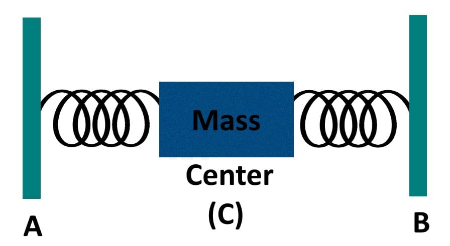
When the vehicle starts to move, the mass will move in the direction opposite to the vehicle’s movement and move towards the backside of the box. (to side B). Once our vehicle reaches a stable speed and reaches the cruising speed, as with our balloon experiment, the mass will come back to the center point C. When the vehicle decelerates and comes to, as you guessed it, it will move front towards side A!
Okay, we are almost there! Lets now put 2 plates of electrodes on sides A and B. and connect a battery to it. It will turn into a capacitor. With one side having a positive charge and the other side having a negative charge with an electric field forming in-between them.
If our mass is made up of a dielectric and it moves in this electric field it is going to disturb it a bit, thus changing the capacitance value of our set up. This change in capacitance is going to be proportional to how fast the box accelerates. Using this data, we can measure the acceleration of any object!
So our accelerometer sensor basically has the above set up with the box with electrodes, springs and mass inside, but in miniaturized form. Over the years as technology improved, the above set up has been made smaller and smaller and now we are in MEMS era.
What are MEMS IMU sensors?
MEMS stands for Micro Electro Mechanical System.
- Micro: because all dimensions are in the micrometer range
- Electro: because we have electrodes inside to make a capacitor and they form the electrical system
- Mechanical: Our Mass and spring form the Mechanical System
- System: Together they form a system to serve a specific purpose, in our case to measure the acceleration.
Okay, that’s how an accelerometer works. Let’s go for gyroscopes now, which is easier to understand since we got the basics of the MEMS system already covered.
How do gyroscopes work?
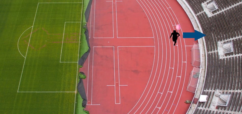
This time let’s take our balloon and go for an imaginary run in our local ground! This time lets run on the curved part of the 400m track and observe how our balloon behaves, looking from the top!
If you look at the balloon from the top, you will notice that it is actually moving away to the side, towards the outer region of the curve as we run the curve (imagining that there is zero wind in any direction, We did not use this experiment for our accelerometer because our balloon will never come to a vertical position once we reach cruising speeds because of the wind resistance )
You can repeat the same experiment with our imaginary train ride also when the train is taking a curved path, the balloon will move out in the direction of the radius, as shown in the picture.
Now take out the balloon and put in our box with mass and spring similar to the accelerometer, the only difference being the fact that it’s now bolted to the floor in another angle so that the mass can move towards the windows of the train, instead of a front and back movement.

So when the train takes a curved path toward the left, the mass moves to the right, and when the train turns right the mass moves left. The more curved the path is and the faster the train is moving, the more the mass is going to move.
Now lets put in our electrodes again and there it is, our Electro-Mechanical Gyroscope that can measure the angular speed, make it’s smaller and we have our MEMS gyroscope!
Now that we have an understanding of how accelerometer and gyroscope works, let’s go ahead and see a little bit about data processing.
IMU data processing
Data processing is basically taking the numbers given out by our sensors and making sense out of them. IMU sensors these days give outputs in terms of digital values as opposed to the analog capacitance change that they experience, making our jobs easier as we don’t have to deal with Analog to Digital conversion (ADC) ourselves (You can read more about the ADC in this article about microcontroller peripherals)
So all we need to do from our side is to take these numbers and use them as needed. There are a lot of algorithms developed at lots of universities that we can use on our projects. All we need to do is implement the mathematical formulas in our codes. As we saw above some applications need the combination of both accelerometer and gyroscope readings like the pedometer, VR headsets, and drones. Usually, a mathematical quantity called quaternions is used to simplify this data to measure the orientation of the object of interest, in other words, to calculate which way our VR headset is facing, like up or down or one of the sides.
What are quaternions and where are they used? Quaternions are basically a mathematical way of combining the data from IMU sensors and presenting it in a way that makes its computation easier in terms of processing power needed.
They can be calculated in 2 ways, either from just the IMU sensor on applications that do not need the direction of heading, or using MARG sensor arrays, where the direction component is useful.
Another problem that usually comes with sensors of any kind is noise. Not the audio noise, but just some data that does not make sense when we compare it to the rest of them.
What is sensor noise?
Let’s take a familiar example of an electronic weighing machine. Now go ahead and measure your weight. Let’s say you weigh 50.0 Kgs. Now take a small weight in hand, say a 100gms, like a phone, and go ahead and measure your weight again. Logic says, the machine should show you 50.1 Kgs, but probably your weighing machine will still say you measure only 50.0Kgs. This is because of filtering. Sensors don’t give out stable accurate data all the time. So even with the same input twice it can give out slightly different output. So the manufacturers of your machine put in some mathematical filter to show you the same value even if the actual output from the sensor changes slightly say +/- 1%.
How to filter sensor noise?
Now let’s get back to our IMU. A sample raw gyroscope reading of your MEMS gyroscope, when placed perfectly still on your table, may look like this
0,1,2
3,0,1
0,2,0
.
.
.
The 1st number is the angular speed in degrees per second about the X-axis, 2nd number is about the Y-axis and the 3rd number is about the Z-axis.
Now like I said, the sensor is lying perfectly still on the table, so what are these minor variations? They are called the sensor noise. They are named so because they can be due to a million different factors and it’s usually easier to filter them out mathematically rather than correct each of the million factors.
Say we use a condition that if the values are between 0 and 3, we take it as zeros. Now after we apply this filter our readings look like this
0,0,0
0,0,0
0,0,0
.
.
.
Which explains the fact it is lying still. The above example is a simple filter, but there are other more complicated ones available, one example for this could be the Kalman filter.
So this is about the data processing side of the IMU sensors.
IMU buying tips
What are the parameters we must see while selecting an IMU sensor?
IMU sensors usually give out digital data as we saw above. There are 2 factors here that we need to see while selecting an IMU sensor for our application.
- Number of bits used in the ADC output and
- The range/sensitivity combination the sensor supports.
Number of bits of ADC output
Basically, these sensors use Analog to Digital conversion, to change the analog physical quantities like voltage and current into digital readable values. The accuracy of these values depends upon the accuracy of the conversion. You can read this article, particularly the analog to digital conversion section of it to understand the process.
Usually, this number of bits is 8, 10,12 or 16bits. To keep it simple, the more the number of bits, the better the accuracy will be.
Range/Sensitivity
Range refers to the amount of acceleration or angular speeds these sensors can measure. For example, the acceleration ranges are typically +/- 2g, 4g, 8g and 16g for acceleration (1g = 9.81m/s2 the acceleration due to gravity). These ranges can also differ from sensor to sensor. Some sensors support multiple ranges where we can change the settings of the sensor to make it use a particular range.
The more the range is the lower the sensitivity and vice versa. For example, if you set the range to be +/= 16g, you can measure changes up to maybe 0.1g, but if you change the range to be +/- 2g, then you can measure changes up to maybe 0.05g.
Don’t worry too much about these numbers as you can always google to find a similar application as yours and figure out which one to get.
You can use this MPU6050 sensor to start with and if you find out you need more sensitivity or data output like quaternions then you can always take a more professional one like this BNO080 sensor from Bosch.
Alright, I will stop here. I hope you guys enjoyed reading this article.
You can email us or contact us through this link if you have any questions or suggestions.
If you liked the post, feel free to share this post with your friends and colleagues!