
In this article, let’s learn about the 9 most essential parts in a Microcontroller and their applications.
What is a Microcontroller made up of? A microcontroller is made up of 2 major parts, the microprocessor, and its peripherals.
What are peripherals? Peripherals are devices that aid the microprocessor to accomplish a given job. In other words, they serve as accessories to the microprocessor. Depending on their location they can be classified into 2 types, if they are located inside the SoC (expands to System on Chip, in other words, its just the IC containing the microprocessor ) of a micro-controller they are called as on-chip peripherals and if they are located outside the SoC but on the same PCB they are called off-chip peripherals.
Let’s start learning about them by first looking at the difference between a microprocessor and a microcontroller.
Microprocessors vs Microcontrollers
The main difference between Microprocessors and Microcontrollers: Peripherals
Microprocessors are basically electronic devices that execute our code. It is made up of integrated circuits and its abilities include doing mathematical and logical computations and controlling the devices connected to it. These days they are commonly referred to using the name ‘cores’. The core by itself cannot do much, and it needs some other devices to serve a useful purpose. These other devices are called peripherals.
In early days these peripherals were bought separately and soldered onto a PCB along with a microprocessor chip to make a useful system that can accomplish a given job. This approach had several disadvantages like
- so much hardware design effort was needed to design a PCB that makes them all go together,
- PCB area/size was too large and it prevented miniaturization and
- lots of software design efforts were needed to integrate the system
The manufacturers began to understand the usefulness of putting all the above-mentioned peripherals in a single IC package. Yes, some of these might not be useful to a given application. Maybe my application does not need ADCs and your application might need ADC and might not need DMA. But the reduced design effort and cost far outweighed the added cost of some unnecessary peripherals. So the job of hardware designers reduced to just finding an SoC that satisfies most if not all of their requirements.
Common embedded peripherals that most systems need include
- GPIO controllers
- Timers
- PWM controllers
- DACs
- ADCs
- Serial Communication Controllers for UART, SPI, I2C, and Ethernet
- Memory
- Interrupt controllers and
- Direct Memory Access controllers (DMA)
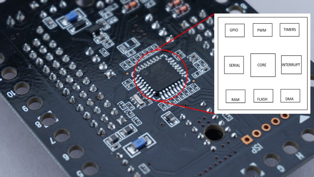
Microcontrollers are simply integrated circuits that have a microprocessor along with some peripherals.
These ICs that come as a package were mostly used in control systems and this resulted in the advent of a set of ICs called microcontrollers.
Adding more peripherals
If a given application needs some peripheral other than the ones given inside the IC package by the manufacturers, they can always be added later. And these peripherals are called external peripherals as they are external to the chip that contains the processor. The ones that are already on the chip are called internal peripherals or on-chip peripherals
If you cannot find a microcontroller that has all the necessary peripherals, you can always buy the peripheral separately and solder it onto the PCB and make it talk to the main SoC, typically using a serial communication standard (like UART, SPI …). A famous example of this is a non-volatile memory. Most SoCs come with a limited amount of flash storage typically in the order of KiloBytes and if we need to store more data, usually a flash chip is added to the hardware design. Then a communication channel is made between the microcontroller and the flash chip (usually SPI or QSPI protocol is used for flash chips) to connect that peripheral to our system.
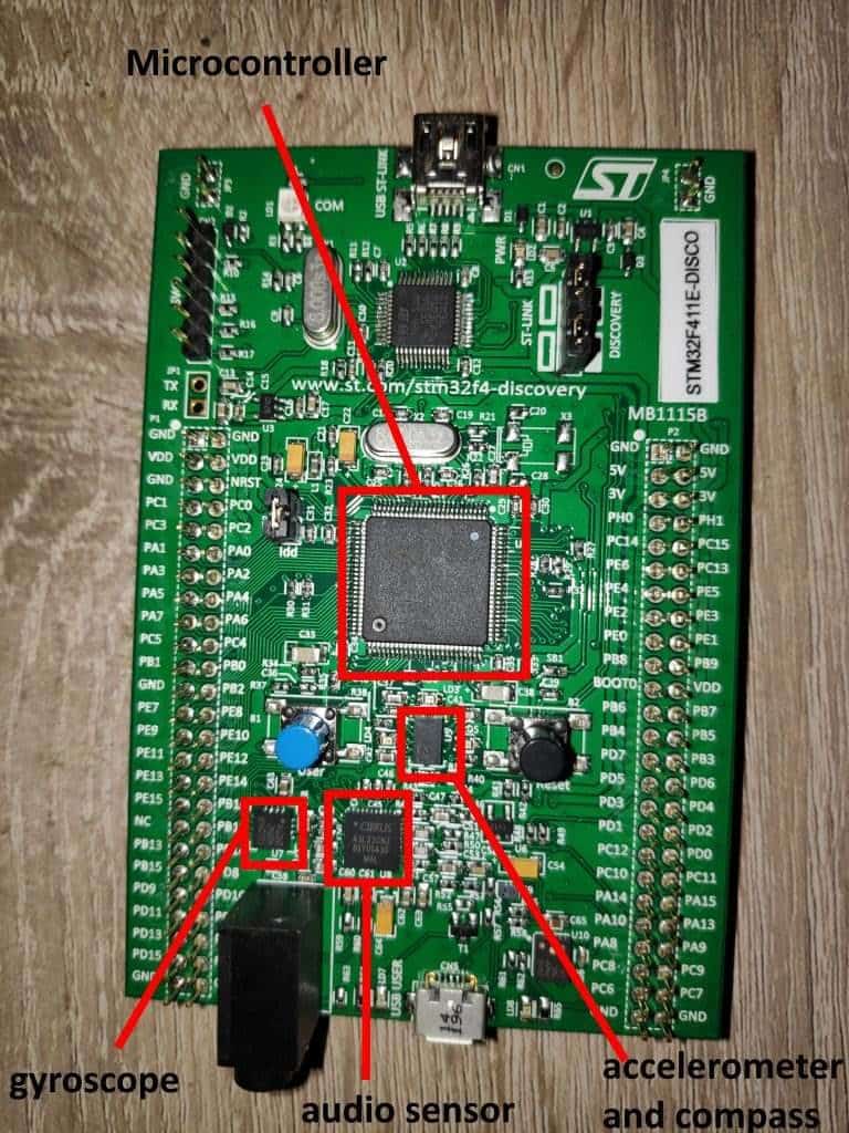
Another example is adding necessary sensors to your application. Almost all SoCs comes with just the temperature sensor on them to monitor the temperature of the chip. Let’s say, you need to record audio in your application then you need to add your own microphone to the design, if you need to measure distances, then you need to add some ultrasonic sensors and so on. The pic below shows the discovery development board from STM microelectronics with its STM32 microcontroller and some external peripherals like an audio sensor, gyroscope sensor, compass, and accelerometer sensors.
Sometimes you may need Bluetooth or Wifi or Ethernet, then you can simply add another chip that implements these protocols and add these functionalities to your hardware.
Your only limitation to adding more peripherals will be the availability of GPIOs and serial communication controllers on the microcontroller, so keep that in mind as you design your board!
Let’s have a look at the functionality of the above-mentioned peripherals in some more detail.
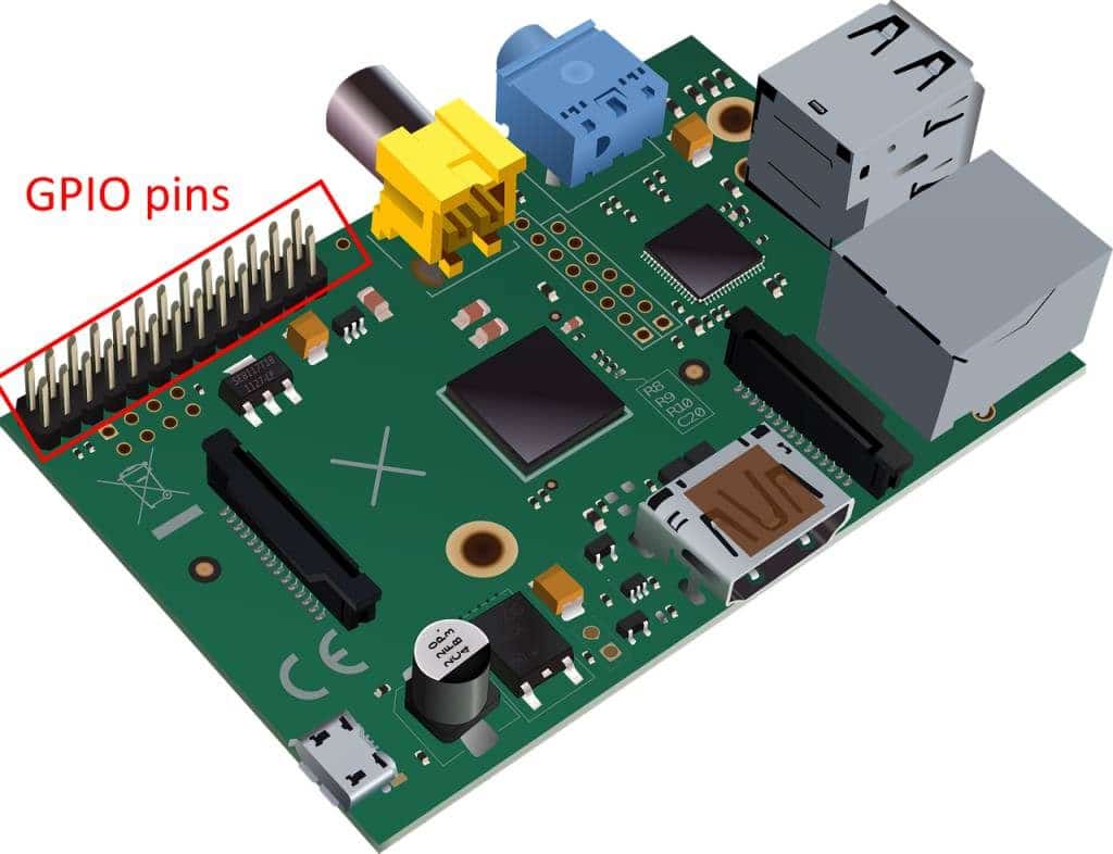
1. GPIO controllers
GPIO stands for General Purpose Input and Output. These refer to the pins that are coming out of the microcontroller SoC.
The basic functionality of a GPIO controller includes
- setting the GPIO pins as either input or output,
- reading the voltage level, if they are set as input
- writing the voltage to 0 or 1 if they are set as output.
- can be routed to other peripherals such as ADCs and DACs to serve some alternate functions as needed by the peripherals.
Generally, a single one of these GPIO controllers are able to control 8 IO pins and a microcontroller can have more than one of these. These units are usually referred to as Ports (Port A is controlled by GPIO controller A, port B is controlled by GPIO controller B,…)
2. Timers
Timing is a crucial part of any embedded system, be it controlling the blinking rate of the LEDs or controlling the sampling rate of the ADCs, or a simple delay on the source code. This need for timing is usually handled by devices called timers.
Timers can operate in 2 modes
- One time mode and
- Periodic mode
One-time mode
In One-time mode, we can set the timer to go off after a particular time duration, say 10 ms. Once started, the timer counts down and once it runs out it notifies the core through a mechanism called interrupts (discussed later in this article)and the timer gets disabled. This action is very similar to using a stopwatch in count down mode.
Periodic mode
In periodic mode, once the timer runs out, it notifies the core, then instead of getting disabled, it automatically reloads the initial value and starts counting down again. Basically, all this mode does extra compared to the One-time mode is just the auto-restart!
There are several types of timers that can be present in an embedded system. Examples cam include general-purpose timers, watchdog timers, and SysTick timers. Each of these is useful in specific scenarios. You can read this article to learn more about timers
3. Pulse Width Modulation (PWM) controllers
These are special kinds of timers that are directly able to control the voltage output at a given GPIO pin.
The microcontrollers are digital devices that can only deal with binary voltage levels, level 0 and level 1. Level 1 can be 1.8v or 3.3v or 5v depending upon the microcontroller design and Level 0 is usually 0v. If we need some other voltages in the middle, let’s say 0.45v, the only way to accomplish this is by turning on and off the pins continuously at a very fast rate so that the average voltage becomes 0.45v. The device that does this is called PWM controllers.
For example, say we have a microcontroller with voltage levels of 0v and 5v and we need 2.5v output. We can use the PWM controller to do that for us by asking it to keep the pin at 0v for 1ms and 5v for 1ms and just alternate between the 2 for as long as we need this 2.5v output.
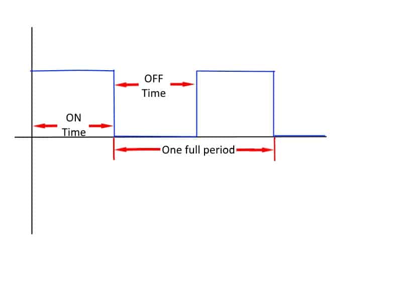
The duty cycle and period are the 2 most important parameters when designing the chip. Duty cycle is the ratio of On-time to Off-time and the period of a PWM output is simply the time duration of one period as shown in the image above.
The most common application of PWM is to drive the LEDs to variable brightness. Other examples include controlling motors, audio amplifiers, and power supplies.
4. Digital to analog converters(DAC)
They take integers (digital numbers) as input and produce an equivalent analog signal as output. PWM controller discussed above does something similar to it, but not exactly, the difference being the fact that it can only produce digital voltage signals. That is, it cannot produce analog signals.
For example, let’s say we need to create a sine waveform signal, then we need to give the DAC a set of numbers as input one by one in with a fixed time interval. Let’s use a 16 point sine wave to accomplish this. Sine function can take input from 0 to 2π, so the 16 points we need are sine(0), sine(π/8), sine(2π/8), sine(3π/8) … sine(15π/8). ( sine(16π/8) becomes sine(2π) which is same as sine(0).
So the resulting 16 points look like this.
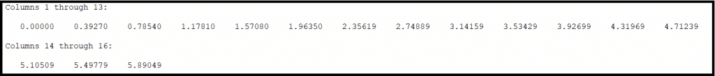
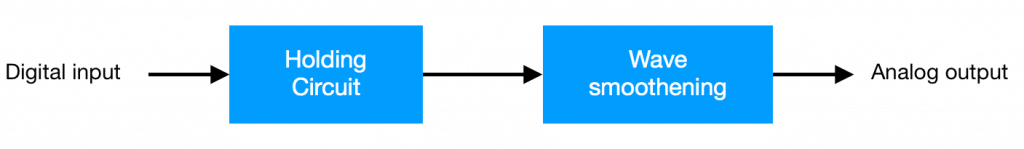
The results are multiplied by 1000 and added with 1024 to get the integers that we need to send to the DAC controller (more details about this conversion in the next section). DACs simply take in this input number and hands it over to its holding module which holds the output voltage of the DAC proportional to the input number. Since we are using a constant interval transmission, we end up with a stepped sine wave as in the picture
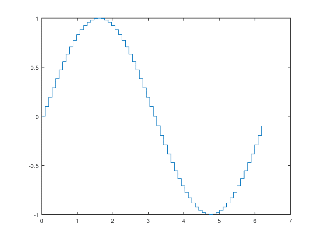
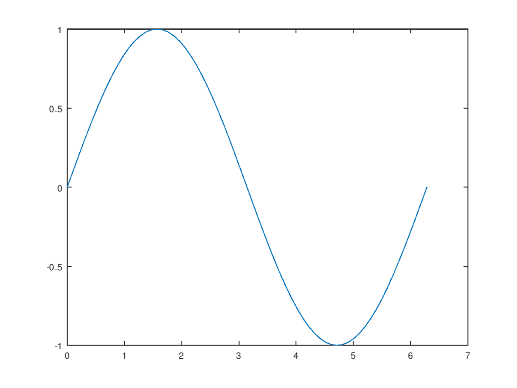
The next step is to put this output through some wave smoothening filters which basically interpolates the sine wave and gives us an output like this
DAC output quality
The quality of the output can be increased by choosing a DAC that accepts a bigger range of numbers as input. For example, an 8 bit DAC can only take 0 to 255, while a 32 bit DAC can take 0 to 4294967295 and hence more accurate outputs!
Our example above assumed an 11 bit DAC (0 to 2045) and that’s the reason we multiplied the results by a 1000 and added 1023 (sine function varies from -1 to 1) so that we can get results in this range of 0 to 2045.
Applications of DAC
DAC is used in all application that involves an analog output. Some famous examples include speakers, medical devices, AC motor drive controllers and analog video equipment.
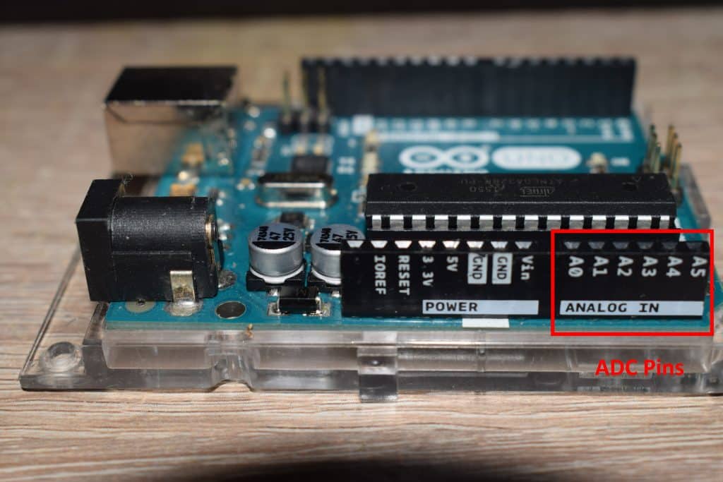
5. Analog to digital converters(ADC)
Anywhere you see analog sensors being used as input, it is usually connected to special pins with an ADC underneath, called analog pins. You can see the pins labeled A0, A1, A2,… in this pic of my Arduino below.
These ADCs are devices that can sense the voltage at a given GPIO pin. It takes an analog voltage and converts it to a digital number. It does so using a method called sampling and quantization.
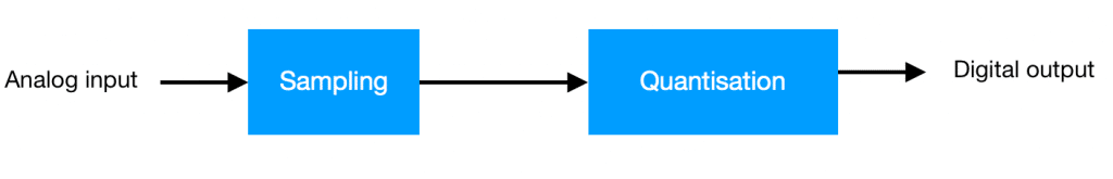
As you can see in the above picture, the process is the exact inverse of what a DAC does, for example here a sine wave is transformed into a series of numbers, which can be used inside the microprocessor for further processing (in case of amplification and recording sound signals) or making decisions (in case of sensor input like battery voltage and temperature sensor)
6. Serial communication Controllers
To talk to the external peripherals, some sort of communication protocol is needed. This is taken care of using devices called serial communication controllers. The most common examples of serial communication protocols include UART, I2C, and SPI. There are several others like I2S, USART, USB, Ethernet, Bluetooth, Wifi and so on. In essence, almost all of the communication protocols we use these days are serial in nature.
Serial vs parallel communication
To understand what serial communication really means let’s see how different it is from parallel communication. Imagine a hollow pipe, and your job is to send a set of 8 balls from one end of the pipe to another. So you start putting them one by one through the pipe. This is the principle behind a serial protocol. Here each ball represents a bit of data (either a zero or a one) and the pipe represents the communication channel which can be a PCB track or a USB cable or an ethernet cable or just air for wireless protocols like WiFi.

Now imagine a set of 8 pipes, and a set of 8 balls, here you can simply send the 8 balls together instead of sending one by one. This is the principal of parallel communication protocols.
Parallel though in paper sounds better than serial, in practical situations, since the balls need to be reordered in their original order, lots of overheads and synchronization issues come up and serial communication is still fast enough and reliable in most scenarios.
7. Memory
There are 2 types of memory
- Primary memory and
- Secondary memory
Primary memory is volatile and holds data and the source code that is presently being processed, while the secondary memory is nonvolatile and used to hold constants and the source code.
You can read about it in more detail in here (also available in the related articles section at the bottom of the article).
8. Interrupt controllers
Interrupt controllers listen to the peripherals for events and reports to the processor once an event occurs.
Lets first talk about what interrupts are by considering some real-life examples of interrupts.
- you are sleeping and in the morning the alarm you set goes off and wakes you up (by interrupting your sleep)
- You are reading a book and your phone rings to alert you of a call (by interrupting your reading session.)
These are 2 examples of day to day interrupts experienced by us humans.
This concept has been ported to embedded systems using special devices called interrupt controllers. I like thinking of them as event listener peripherals. Their main job is to listen to the events generated by the other peripherals and report them to the processor.
Examples of events that can produce interrupts include
- GPIO reads 1 or 0
- Timer countdown reached 0
- Serial communication received a packet of data and
- DMA has completed a transfer
The particular event that we need to listen to can be programmed by us and unnecessary events can be ignored.
Once a registered event happens, the interrupt controller goes and tells the CPU about it, so that the CPU can take appropriate action.
For example, consider a simple circuit where one pin is configured as digital input and another as digital output as shown in the figure.
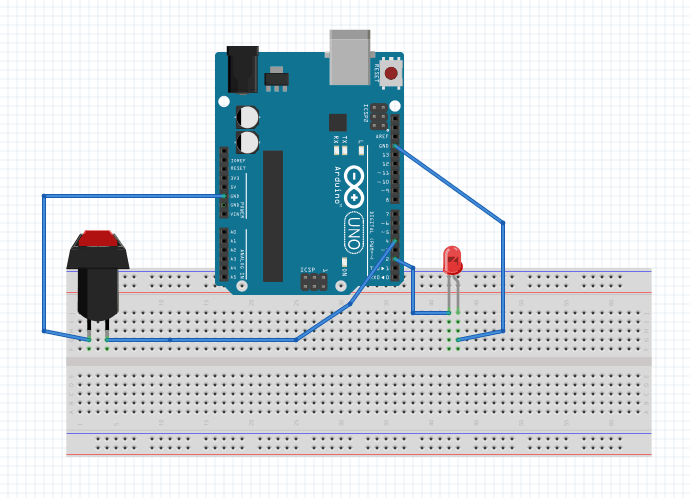
Here the job of the system is to light up the LED if the button is pressed. We can write code to achieve this functionality in 2 ways.
Polling
This first method is that we continuously see if the button is being pressed and once it is, then we turn ON the LED. This approach of doing things is also called polling. The code snippet below shows how to implement this method.
int main()
{
    gpio_init(LED, output);
    gpio_init(Button, input);
    while (true)
    {
        if (gpio_read(Button) == 1) {
              gpio_write(LED, 1);
        }
        else {
             gpio_write(LED, 0);
        }
    }
    return 0;
}
This is analogous to look at the clock all night and getting out of the bed as soon as its 6 AM and turns on the light! So we wasted the entire night without sleeping and wasted a lot of energy, which is a very inefficient way of doing it!
Interrupts
Instead, the better way to do it is to go ahead with our sleep and just set an alarm(/interrupt) to wake us up at 6 AM.
On the microcontrollers, we can accomplish this by setting up the interrupt controller to tell the CPU that the button has been pressed.
The interrupt controller then listens to the button press on the GPIO input pin and once the button is pressed, it wakes up the microcontroller and executes a function that turns the LED on for us. Once the LED is ON, the CPU gets to go back to sleep. (unlike us who need to get to work!)
This method has an energy-efficient implementation since the CPU is sleeping most of the time.
But you may ask, what about the interrupt controller, won’t is waste energy by seeing if the button is pressed or not 24/7? The answer to that question is yes the interrupt controller will consume some power, but CPU can consume 100’s of times more energy than a typical interrupt controller.
This mechanism of doing things is called interrupts.
The code snippet shown below shows the implementation of interrupts to achieve the same result.
void LED_ON_ISR()
{
    gpio_write(LED, 1);
}

void LED_OFF_ISR()
{
    gpio_write(LED, 0);
}

int main()
{
    gpio_init(LED, output);
    gpio_init(Button, input);
    init_interrupt(Button_pressed, LED_ON_ISR);
    init_interrupt(Button_released, LED_OFF_ISR);

    while (true)
    {
        sleep();
    }
    return 0;
}
Here in the main function, as soon as everything is initialized, the CPU goes to sleep and only wakes up when the interrupt controller sees a button press or button release event.
As you can see, the code looks more complicated once interrupts came into the picture, but even setting up your alarm needs extra work, that does not mean it is the best way of getting a good night’s sleep!
So whenever there is an opportunity, its good practice to use interrupts instead of polling. (when laziness to implement more code kicks in, just remember the sleep and alarm analogy!)
Interrupt vector table
In the above example, if button1 is pressed then LED1 must be lit and if button1 is released then LED1 must be turned off. The CPU needs a way to figure out which ISR should be called on button press and release. That is there needs to be a mapping between a given Interrupt request (IRQ) and its Interrupt Service Routine (ISR)
IRQ stands for Interrupt ReQuest and ISR stands for Interrupt Service Routine. These are just technical names, so don’t stress too much over it. Just remember that the interrupt controller waking up the CPU is a ReQuest to service an Interrupt. (Or its an IRQ) , the function that gets executed once IRQ comes is the ISR.
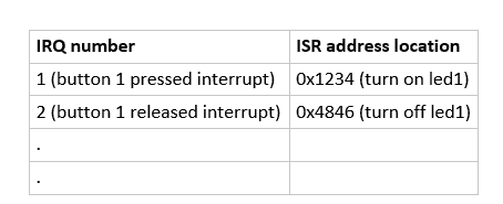
The interrupt vector table is simply a table with 2 columns, column1 contains the interrupt number (IRQ number) and column2 contains the address of the function to be executed (ISR) if a given interrupt occurs. Once an interrupt comes (the interrupt number comes in with the IRQ), the CPU simply checks this table to get the address of the ISR and then it goes and runs the appropriate code.
In the previous example, we had 2 IRQs: Button_pressed and Button_released, connected to 2 ISRs: LED_ON_ISR and LED_OFF_ISR respectively.
9. Direct Memory Access Controller
The 3 main types of operations a microprocessor perform include arithmetic operations, logical operations and data move operations. By data move operations I mean transferring data from one memory location to another, for example from UART buffer to the RAM and vice versa.
Imagine you own a courier company and you hire an awesome programmer for 100 bucks per hour. His main job includes, of course, creating awesome code for your courier website.
But he is getting constantly interrupted by customers coming in all day with parcels, and he is wasting his time collecting those parcels and keep them in storage for transport later. So you decide to hire another person, for say, 20 bucks/hour to take care of these simple parcel reception duties, while your awesome programmer can focus on the job he is good at, this way your overall productivity will increase immensely and so will your revenue!
This analogy is perfect for describing DMA. Here the microprocessor is your awesome programmer, the customer coming in is say UART interrupts to the microprocessor, UART data is the parcels and the second person hired is the DMA controller.
If a given application deals with large amounts of data transfer then all of the precious microprocessors time will go on these data transfers, which will result in a very inefficient process both in terms of power consumption and execution times. Hence it’s a good idea to transfer the data moving responsibilities to a special device called the DMA controller, while the processor can carry on doing it’s more intensive math operations!
These are the 9 essential microcontroller peripherals that you will probably come across very frequently as an embedded engineer or a hobbyist. Having a good understanding of them is very important as you can have a good overview of what’s possible and what’s not with your hardware. This way you can pick the right microcontroller for a given application.
Hope this post was helpful and the next time you read a datasheet of a microcontroller, make sure you check out its peripherals to understand its capabilities.
You can email us or contact us through this link if you have any questions or suggestions.
If you liked the post, feel free to share this post with your friends and colleagues!